Accurate models created from millions of data points obtained from mineshaft scanners save time and prevent errors when planning, installing and maintaining infrastructure. Traditional surveying gathers limited data in most environments, which may impact on accuracies in material estimations and engineering plans.
Mines are legally obliged to do regular visual inspections of their shafts. A manual process interrupts normal operation for several hours, which results in a loss of production and revenue. It is a tedious process that can lead to an oversight of defects.
Sight Power (www.sight-power.com), a company specialising in the development of analytical information and data modelling systems for the mining, oil and gas industries, approached Parsec to develop an automated solution to prevent undue interruption of the production process yet meet the legal requirements. Parsec took on the challenge to design and develop a concept demonstrator of the Mineshaft Scanning System (MSSS).
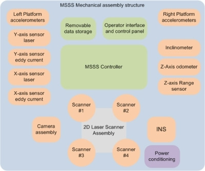
The MSSS main components consist of a controller connected to various geo-reference and optical sensors, the mechanics hosting these entities and an operator console for control and maintenance of the system. Parsec subcontracted the mechanical design and construction of the system to MMS Technology (www.mmstechnology.co.za).
Parsec's objective with the MSSS project was to provide a development service to its client that provided it with a platform to prove a concept. Once the concept has been proven, follow-up development work may potentially evolve, which can be embedded into the client's product. The expectation is that the development of the demonstrator will, in the long term, allow Parsec to expand its activities in the industrialisation and outsourced manufacturing of the product.
Comprehensive approach to achieve the end goal
The main requirement of the MSSS is to provide a detailed 3D scan of the mineshaft environment (this includes the shaft lining, steelworks, cables, ropes and other construction elements) with a predefined density of reflected points. Data gathered from each laser sample of the laser scanner is time- and geo-tagged to enable offline reconstruction and processing of the shaft image.
The project consists of three phases, namely a definition, implementation, and integrate and test phase.
The definition phase duration was 10 months, and was initiated in July 2011 with an extensive feasibility study during which academics specialising in the field of inertia were consulted. Various laser scanners, Inertial Navigation Systems (INS), accelerometers, inclinometers, distance sensors (eddy, laser, encoders) and cameras available in the market were evaluated during this process. This included visits to manufacturers to obtain first-hand knowledge of the products.
This was followed by the creation of a user requirement specification as well as a system specification. Enterprise Architect, a high-performance modelling, visualisation and design platform, was used to dissect the requirements into unified modelling language (UML) use cases. These use cases were further elaborated on in software, hardware and mechanical design documents used by the development engineers. It was decided to do validation of the sensors and collect data as early as possible during the development process. Test applications and mathematical models were created to assist with this de-risking initiative.
The implementation phase started directly thereafter, and produced a laboratory prototype model, which, at present, is being exercised in the laboratory. This phase lasted for nine months, and the project is currently making the transition from implementation to the integration and test phase.
As with Parsec's total project portfolio, this project was also executed under the Project Management Body of Knowledge (PMBoK) framework.
High-bandwidth FPGA PMC module to overcome shortcomings of the OS
The design team was faced with some interesting challenges. Being a concept demonstrator and taking into account time-to-market, the decision was taken to use off-the-shelf components wherever possible. An industrial PC, running Microsoft Windows OS, was used as a controller, which did not guarantee the timing requirements aimed for. To overcome this obstacle, one of Parsec's commercial products (the PM432 high-speed, high-bandwidth FPGA PMC Module, (www.parsec-group.com/parsec/downloads/Parsec_PM432.pdf) was used in the controller. This module very accurately provides PCI interrupts to the software for timing sensor sampling and external clocking for sensor synchronisation.
The logistics of setting up a test environment for the product was another challenge the design team was faced with. The lab constraints forced the team to assemble the scanner horizontally as opposed to the vertical position it is intended to operate in. Rails had to be constructed for the scanner to move on and a cranking mechanism was introduced to simulate the rough movement experienced in the mining environment. This set-up proved to be adequate for demonstrating the concept under investigation.
One of the requirements of the project was for Parsec to provide its customer with reliable data recorded from the various optical and geo-reference sensors. This entails producing repeatable scans where the accuracy between scans is within the design specification. Mathematical models were built in Matlab to do post-processing of the recorded data. This enabled the development team to identify synchronisation and latency issues at an early stage and take corrective measures.
It was always going to be a challenge to synchronise data originating from different sensors. The design team had to go through a number of iterations before accomplishing the goals set out in the requirements. The mathematical models used during data analysis were crucial in fine-tuning the system. Extensive testing was also done on a sub-system level throughout the project. A test application was written for each sensor type to validate the driver and get a feeling for its accuracy and responsiveness.
Parsec prides itself on its ISO9001-accredited processes, which guided this project through the different phases of its life cycle. Regular communication with the customer also proved helpful to manage expectation on progress and delivery.
Conclusion
Through developing the concept demonstrator for an automatic mineshaft scanner, Parsec has proven its ability to supply a customised, all-inclusive solution to its customer. The company is well positioned to be involved in the subsequent phases of the project, which will cover mine testing and the development of a production unit.
Valuable lessons learned include the importance of de-risking throughout the project life cycle. It is important to validate each sub-system as soon as possible and identify potential problems.
Share
Parsec
Parsec is a technology force capable of developing, manufacturing and supplying state-of-the-art embedded solutions in the form of sub-systems or products to a wide spectrum of clients in the global defence/aerospace, telecommunications, industrial market and mining sectors.
Its purpose is to enhance the competitiveness of its partners and clients by enabling them to remain focused on their core competencies, while relying on Parsec's expertise, capabilities and value-added services. It, therefore, promotes a strategy to partner with other product or service companies that outsource their design and/or production requirements to Parsec.
Editorial contacts